Robust DC Motor
Permanent Magnet Motors convert electrical energy into mechanical motion using a magnetic field created by permanent magnets. Unlike induction motors, they do not need rotor current to produce torque. This reduces rotor copper losses and can improve efficiency, especially under variable-speed operation. The basic design sounds simple. The engineering is not.
The International Energy Agency’s Global EV Outlook 2025 reports that global electric car sales exceeded 17 million in 2024. This rapid growth increases demand for compact, efficient traction motors. The U.S. Department of Energy also identifies motor-driven systems as major industrial electricity users, making efficiency improvements commercially important. These figures explain why Permanent Magnet Motors appear in electric vehicles, robotics, compressors, pumps, and precision manufacturing equipment.
A typical motor contains a stator, rotor, magnets, bearings, sensors, and an electronic drive. Alternating current creates a rotating magnetic field in the stator. The rotor magnets follow that field and produce torque. Stronger magnets can deliver high power from a smaller frame. However, the technology has limitations. Rare-earth magnets can raise cost and supply-chain concerns. High temperatures may weaken magnetic performance. Control software also affects real-world efficiency. A laboratory rating is not the whole story. Installation, cooling, loading, and maintenance matter. This article examines how Permanent Magnet Motors work, where they perform best, and why engineers must balance efficiency, reliability, cost, and material availability. It also questions a common assumption: higher efficiency does not automatically mean the best solution for every application.
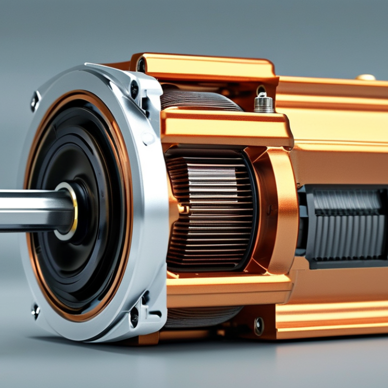
Permanent magnet motors use embedded or surface-mounted magnets to create the rotor’s magnetic field. Unlike induction motors, they do not need rotor current to produce torque. This reduces electrical losses and improves power density. Common types include surface permanent magnet motors, interior permanent magnet motors, and electronically commutated motors. Each design suits different speed, torque, and control requirements.
Efficiency is the key issue. IEC 60034-30-1 classifies IE4 as Super Premium Efficiency and IE5 as Ultra Premium Efficiency. These ratings apply under defined test conditions, not every operating point. The International Energy Agency estimates that electric motor systems consume roughly half of global electricity. Even small efficiency gains can therefore produce substantial energy savings across pumps, fans, compressors, and conveyors.
IE5 performance is possible with permanent magnet technology, especially at variable speeds and partial loads. However, the motor alone does not guarantee system efficiency. The inverter, gearbox, cooling method, and load profile also matter. Real installations are messier. A 2023 industrial efficiency analysis from the IEA stresses that system-level optimization often delivers greater savings than equipment replacement alone. Engineers should check measured load data, thermal limits, and maintenance records before selecting an IE4 or IE5 motor. The distinction is easy to oversimplify. A higher label can still disappoint when the motor is poorly sized, frequently overloaded, or operated far from its efficient range.
A permanent magnet motor uses fixed magnetic fields to create rotor torque. NdFeB magnets provide this rotor flux without continuous excitation current. Their energy products commonly range from 30 to 52 MGOe. This value describes maximum magnetic energy density, not motor output power. Higher MGOe can support compact designs, but geometry still controls performance.
Magnets may sit on the rotor surface or inside its steel core. Their north and south poles establish flux across the air gap. Stator windings then create a rotating magnetic field. The rotor follows that field through magnetic attraction and repulsion.
In a well-designed motor, the rotor turns smoothly and produces strong torque at low speed. Small air gaps matter. Leakage flux matters too.
Real machines are less perfect than textbook diagrams. Heat can weaken NdFeB magnets, especially during overload or poor cooling. The 30–52 MGOe range also requires careful temperature selection and demagnetization checks. Engineers verify flux with electromagnetic simulation, prototype testing, and temperature measurements. A higher grade is not always the better choice. It may increase cost, mechanical stress, or sensitivity to manufacturing tolerances. One easy mistake is treating magnet strength as the entire design. Rotor shape, steel saturation, winding current, and control timing also decide how effectively the magnets create useful torque.
Permanent magnet motors use a rotor carrying permanent magnets and a stator wound with copper coils. Their operation is quiet, efficient, and mechanically direct.
When a controller sends three-phase AC through the stator, each current creates a changing magnetic field. Together, these fields form a rotating field inside the air gap. The rotor magnets follow that field because opposite poles attract and like poles repel. This alignment produces synchronous torque, with no average slip during steady operation.
A two-pole design completes one electrical cycle per mechanical revolution. An eight-pole design needs four electrical cycles for one mechanical revolution. That difference affects inverter frequency, control resolution, and high-speed performance. Torque grows when the stator field leads the rotor by a controlled angle. Too little angle wastes available magnetic force. Too much can cause instability or excessive current.
The current waveform must match rotor position closely. Position sensors can provide feedback, while sensorless control estimates position from voltage and flux. In a workshop test, a small timing error often appears as extra heat before obvious vibration. Copper resistance, iron loss, saturation, and magnet temperature also reduce the ideal result.
The simple picture is useful, but incomplete. Real motors are less perfect. Designers must balance pole count, winding layout, cooling, and inverter limits for the intended speed range.
What Are Permanent Magnet Motors and How Do They Work?
Permanent magnet motors use magnets embedded in, or attached to, the rotor. These magnets create a steady magnetic field without rotor windings. The stator contains copper coils arranged around the rotor. An electronic drive sends controlled current through those coils, creating a rotating magnetic field.
The drive sets motor speed by controlling electrical frequency. For example, increasing frequency makes the magnetic field rotate faster. The rotor follows that field at nearly the same speed. This is synchronous operation. Unlike an induction motor, the rotor does not need slip to produce torque. Speed depends mainly on frequency and the motor’s pole count.
The drive also controls current magnitude and timing. Current affects torque, while timing determines the rotor’s magnetic angle. A position sensor can report the rotor angle directly. Sensorless control estimates it from voltage and current signals. Both methods require careful tuning.
A commissioning lesson matters here. A small position error can cause noise, vibration, or weak starting torque. The motor may sound fine at low speed, then behave poorly under load. Engineers often check phase current, temperature, acceleration response, and encoder alignment. Above the rated speed, field weakening reduces magnetic influence and limits voltage demand. This expands speed range, but torque usually falls. The simple explanation is useful, yet incomplete. Real motors also face magnet temperature limits, inverter delays, and sudden load changes.
| Data Dimension | Permanent Magnet Motor | Induction Motor | Electronic Drive or Control Implication |
|---|---|---|---|
| Operating Principle and Motor Construction | |||
| Source of Rotor Magnetic Field | Permanent magnets mounted on or embedded in the rotor provide the main magnetic field without requiring rotor current. | The rotor magnetic field is created by current induced in the rotor conductors by the rotating stator field. | The drive must establish the correct stator current magnitude and electrical angle to produce torque efficiently. |
| Rotor Electrical Losses | Ideally, the permanent-magnet rotor has no rotor copper loss because no continuous rotor current is required. | Rotor current produces I²R losses, which increase with load and contribute to rotor heating. | Lower rotor losses can improve efficiency and reduce cooling requirements, but the inverter and stator still produce losses. |
| Common Motor Types | Interior permanent-magnet motor, surface-mounted permanent-magnet motor, and permanent-magnet synchronous motor. | Squirrel-cage induction motor and wound-rotor induction motor. | Permanent-magnet motors generally require a compatible variable-frequency inverter for controlled starting and operation. |
| Starting from a Fixed-Frequency Supply | A synchronous permanent-magnet motor cannot normally start itself directly from a fixed-frequency AC supply because the rotor must be synchronized with the rotating field. | A squirrel-cage induction motor can generally start directly from a suitable fixed-frequency AC supply, subject to starting-current and load limitations. | An inverter supplies a controlled frequency ramp and rotor-position-based current to start a permanent-magnet motor smoothly. |
| Rotor Position Information | Rotor position may be measured with a sensor or estimated from electrical behavior, depending on the control method. | Rotor position is not always required for basic scalar control because slip naturally produces rotor torque. | Field-oriented control can use an encoder, resolver, Hall sensors, or sensorless estimation to align the stator field with the rotor magnets. |
| Speed, Frequency, and Slip | |||
| Synchronous Speed | The ideal mechanical speed is directly related to electrical frequency and pole count: ns = 120f / P, where ns is in revolutions per minute, f is frequency in hertz, and P is the number of poles. | The stator field also rotates at ns = 120f / P, but the rotor runs slightly below this speed during motoring operation. | The inverter changes output frequency to set the commanded synchronous speed. |
| Typical Operating Slip | Steady-state speed is nearly synchronous, so mechanical slip is approximately zero under normal operation. Small angle and speed differences occur during transients and control errors. | Positive slip is required to induce rotor current and produce torque. Rated-load slip is commonly a few percent, but the exact value depends on motor design and rating. | For a permanent-magnet motor, speed is controlled primarily by commanded electrical frequency and rotor synchronization rather than by intentional induction-motor slip. |
| Example Synchronous Speed | At 50 Hz, a two-pole motor has a synchronous speed of 3,000 rpm; a four-pole motor has 1,500 rpm. | The same 50 Hz, four-pole induction motor may operate below 1,500 rpm at load because slip is necessary for torque production. | Changing the inverter frequency changes the target synchronous speed; the pole count remains fixed. |
| Speed Regulation | Very good speed regulation is possible when the inverter maintains rotor-field synchronization and uses closed-loop feedback when required. | Open-loop speed changes with load because additional slip is needed to produce additional torque. | Closed-loop speed control measures or estimates speed and adjusts frequency, voltage, and current to reduce speed error. |
| Torque and Power Behavior | |||
| Torque Production | Torque is produced by interaction between the stator magnetic field and the rotor permanent-magnet field. Interior-magnet designs can also produce reluctance torque. | Torque is produced by interaction between the stator field and the induced rotor field. Rotor current must be present for normal motoring torque. | Vector control regulates torque-producing current, commonly called q-axis current, while separately managing flux-producing current. |
| Low-Speed Torque | Can provide strong low-speed torque when the inverter accurately controls current and rotor position. | Can provide strong starting and low-speed torque, but performance depends on voltage, frequency, rotor resistance, and control method. | Field-oriented control or direct torque control can provide rapid torque response over a wide speed range. |
| High-Speed Operation | Speed above base speed generally requires field weakening by applying current that reduces the effective air-gap flux. Voltage and magnet-retention limits must be respected. | Above base speed, the drive commonly enters a voltage-limited region with reduced available torque, while slip continues to contribute to torque production. | The inverter limits voltage, current, motor speed, and magnet or rotor stress during field-weakening operation. |
| Regenerative Braking | Can generate electrical power during deceleration when the drive controls the motor so that electromagnetic torque opposes rotation. | Can also regenerate, but the drive and operating conditions must create the required torque and manage the DC-bus energy. | A regenerative drive returns energy to the supply or directs it to a braking resistor or energy-storage system. |
| Efficiency, Control, and Application Considerations | |||
| Efficiency Characteristics | Often achieves high efficiency because rotor copper losses are largely eliminated; actual efficiency still depends on stator copper loss, iron loss, mechanical loss, inverter loss, and operating point. | Efficiency is reduced by rotor copper loss in addition to stator, iron, mechanical, and inverter losses. | Efficiency maps are more meaningful than a single value because efficiency changes with speed, torque, temperature, and switching strategy. |
| Power Factor | Can achieve a high power factor with suitable current-angle control, although magnet geometry, saliency, and operating point affect the result. | Power factor is typically lower at light load because magnetizing current is required to establish air-gap flux. | The inverter controls current phase and magnitude, but the electrical supply still sees inverter input power factor and harmonic effects. |
| Thermal Management | Rotor heating is generally lower, but stator windings, bearings, magnets, and the inverter still require thermal management. | Both stator and rotor losses contribute to heat; rotor heat can be difficult to remove from a squirrel-cage rotor. | Drive protection commonly monitors current, estimated temperature, speed, and operating time in overload conditions. |
| Risk During Faults | When the rotor turns, the magnets can induce back electromotive force even if the inverter is disabled. Short-circuit current and demagnetization risk must be considered. | With the supply disconnected, the rotor does not normally produce sustained voltage in the same way as a permanent-magnet rotor. | Protection may include controlled shutdown, short-circuit management, overvoltage protection, and safe handling of regenerated energy. |
| Typical Control Methods | Sinusoidal commutation, field-oriented control, direct torque control, and sensorless or sensor-based synchronous control. | Volts-per-hertz control, sensorless vector control, closed-loop vector control, and direct torque control. | Advanced vector control coordinates three-phase voltage and current to regulate speed, torque, flux, and power limits. |
| Main Design Trade-Off | High efficiency, compact size, and excellent controllability must be balanced against magnet cost, thermal limits, inverter dependence, and demagnetization risk. | Robust construction, simple rotor design, and broad availability must be balanced against rotor losses, slip, and lower light-load power factor. | Motor selection should consider duty cycle, speed range, overload requirement, braking method, ambient temperature, and drive compatibility. |
What Are Permanent Magnet Motors and How Do They Work?
Where PMSMs, BLDC Motors, and PM Generators Exceed 90% Efficiency
Permanent magnet motors use fixed magnetic fields from embedded or surface-mounted magnets. These magnets create rotor torque without continuous electrical excitation. That small change reduces rotor copper losses and improves power density. In practical systems, efficiency above 90% is achievable within a carefully selected speed and load range. It is not a permanent guarantee.
PMSMs usually deliver smooth torque through sinusoidal current control. They suit pumps, compressors, robotics, and electric traction systems. BLDC motors use electronic commutation and often produce stronger torque ripple. Their simpler control can reduce system cost. Both designs benefit from accurate position sensing, low-resistance windings, and suitable cooling. A hot winding quietly consumes efficiency.
Permanent magnet generators can exceed 90% efficiency when mechanical speed, magnetic flux, and electrical loading remain well matched. Wind turbines and compact water turbines often use this advantage. The generator may still lose energy through bearings, iron cores, cables, and power electronics. Measurement also matters. A laboratory result can look excellent, while a dusty field installation performs differently. Engineers should test the complete system, not only the motor or generator. The 90% figure is useful, but sometimes too convenient.verter.
Representative peak-efficiency ranges for PMSMs, BLDC motors, and permanent-magnet generators
Permanent-magnet machines create magnetic flux with permanent magnets, reducing rotor excitation losses and enabling high efficiency. The ranges shown are representative engineering values; actual efficiency depends on power rating, speed, load, cooling, control method, and operating conditions.
: It uses magnets on or inside the rotor to create a constant magnetic field. The rotor needs no electrical winding current. This reduces rotor losses and can improve power density.
Three-phase current flows through stator coils. These coils create a rotating magnetic field. The rotor magnets follow it, producing synchronous torque. The timing must be accurate.
Common designs include surface-mounted, interior, and electronically commutated motors. Each design suits different speeds, torque demands, and control methods. No single design fits every machine.
IE4 means Super Premium Efficiency. IE5 means Ultra Premium Efficiency. These ratings come from defined test conditions. They do not describe every operating point.
Yes, especially during variable-speed operation and partial-load conditions. However, the motor alone cannot guarantee system efficiency. The inverter, gearbox, cooling method, and load profile also matter.
The drive changes electrical frequency. A higher frequency makes the magnetic field rotate faster. The rotor follows with almost no steady-state slip. Speed depends mainly on frequency and pole count.
A two-pole motor completes one electrical cycle per mechanical revolution. An eight-pole motor needs four electrical cycles per revolution. Pole count affects inverter frequency, control resolution, and high-speed behavior.
Incorrect rotor-position timing may cause noise, heat, vibration, or weak starting torque. The motor can sound normal at low speed, then struggle under load. Check phase current, temperature, acceleration, and sensor alignment.
Review measured load data, thermal limits, operating speed, and maintenance records. Check the inverter, gearbox, cooling, and actual load profile. A higher efficiency label can still disappoint. Sizing is easy to underestimate.
Permanent Magnet Motors are electric machines that use permanent magnets to create the rotor’s magnetic field, eliminating the need for rotor windings and reducing electrical losses. Many designs use high-energy NdFeB magnets, typically with energy products around 30–52 MGOe, to produce strong, compact rotor flux. Depending on their construction and control method, they include permanent magnet synchronous motors, brushless DC motors, and permanent magnet generators. These machines are commonly associated with IE4–IE5 efficiency levels and can exceed 90% efficiency in suitable operating conditions.
During operation, alternating current in the stator windings creates a rotating magnetic field. The permanent-magnet rotor follows this field synchronously, producing torque without the slip required by induction motors. Electronic drives regulate voltage, current, frequency, and commutation, allowing precise speed control, smooth starting, and efficient operation across a wide range. Designs with two to eight poles can be adapted for different speed and torque requirements, making them useful in industrial equipment, renewable-energy systems, pumps, fans, and advanced motion-control applications.
