Robust DC Motor
Precision Motors are built for controlled movement, not merely rotation. They convert electrical energy into carefully measured mechanical motion. A standard motor may spin continuously. A precision motor must also stop accurately, repeat its position, and respond predictably under changing loads.
Nikola Tesla, a pioneer of electrical engineering, once said, “The present is theirs; the future, for which I really worked, is mine.” His words fit this field surprisingly well. Modern Precision Motors combine Tesla’s electrical principles with sensors, feedback systems, digital controllers, and advanced materials. Together, these parts manage torque, speed, angle, and acceleration with remarkable consistency.
Inside the motor, electromagnetic forces create rotation. Magnets and windings interact when current flows through the coils. A controller adjusts that current many times each second. An encoder then reports the shaft’s position. The system compares the actual position with the desired position and corrects the error.
Small errors matter.
A fraction of a degree can affect a robotic joint, camera lens, medical pump, or semiconductor tool. Engineers therefore select motors according to torque, speed, heat, vibration, duty cycle, and available space. There is no universal “best” motor. That assumption is convenient, but wrong.
Some designs use brushless DC technology. Others rely on stepper motors, servo motors, or linear motors. Each offers useful strengths and frustrating limitations. Precision does not remove mechanical wear, calibration drift, or installation mistakes. It only makes those problems easier to measure.
Understanding how Precision Motors work requires both theory and practical observation. The datasheet matters. So does the sound of a bearing, the warmth near a winding, and the movement under real operating conditions.
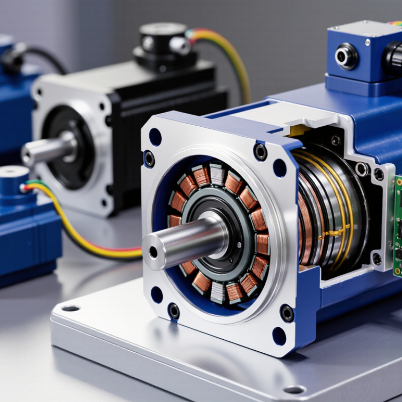
Precision motors are electromechanical devices designed to deliver controlled motion with minimal positional error. Unlike general-purpose motors, they prioritize repeatability, torque stability, and predictable response. Their applications include robotic joints, semiconductor equipment, medical instruments, and inspection systems.
The core characteristics are accuracy, resolution, low backlash, and strong thermal stability. A feedback sensor measures shaft position or speed. The controller then compares actual movement with the commanded value. It adjusts current almost instantly. This creates a closed-loop system. However, no motor is perfectly precise. Heat, vibration, friction, and worn couplings still create small errors. That practical limitation deserves more attention.
The International Federation of Robotics reported 541,302 industrial robot installations worldwide in 2023. Such equipment depends on repeatable motion across thousands of operating cycles. A 2024 market analysis from Mordor Intelligence also forecasts steady growth in precision motor demand through the decade, driven by automation and compact electronic equipment. These figures show market momentum, but they do not guarantee performance. Engineers must check encoder resolution, rated torque, acceleration, duty cycle, and environmental conditions. A motor can meet a published accuracy value in a laboratory and perform differently on a hot production line. That gap is easy to underestimate.
| Dimension | Key Point | Definition, Working Principle, or Typical Characteristics |
|---|---|---|
| Definition | Precision motor | A motor designed to provide highly controlled rotation or linear motion with predictable speed, position, torque, and repeatability. It is normally integrated with a drive, feedback device, and mechanical transmission when closed-loop accuracy is required. |
| Motion conversion | Electrical energy to mechanical motion | The motor converts electrical power into electromagnetic force. Interaction between the stator’s magnetic field and the rotor’s magnetic field or induced current produces torque, causing the shaft or actuator to move. |
| Control architecture | Open-loop and closed-loop control | Open-loop systems command motion without measuring the actual output. Closed-loop systems use feedback from an encoder, resolver, or other sensor to compare commanded and actual motion and automatically correct errors. |
| Common motor types | Servo, stepper, brushed DC, and brushless DC motors | Servo motors are optimized for feedback-based motion control; stepper motors move in discrete angular increments; brushed DC motors use mechanical commutation; and brushless DC motors use electronic commutation with reduced brush wear. |
| Positioning method | Feedback-based positioning | A controller calculates the difference between the target position and the measured position. It then adjusts current, voltage, or commutation timing to reduce position error and maintain the commanded trajectory. |
| Speed control | Closed-loop speed regulation | The drive monitors rotational speed through feedback and changes motor current or voltage to compensate for load variations. Stable speed regulation is important in scanning, winding, feeding, and inspection equipment. |
| Torque production | Current-related torque | In many motor designs, electromagnetic torque is approximately proportional to motor current within the rated operating range. The drive regulates current to control acceleration, deceleration, and load-handling capability. |
| Position resolution | Commanded motion increment | Position resolution depends on motor construction, encoder counts, controller interpolation, and mechanical transmission. A smaller command increment can improve motion smoothness, but it does not automatically guarantee equivalent absolute accuracy. |
| Accuracy | Difference from the target position | Accuracy describes how closely the actual position, speed, or movement matches the commanded value. It is affected by calibration, backlash, friction, thermal expansion, structural deflection, sensor error, and control tuning. |
| Repeatability | Consistency of repeated motion | Repeatability indicates how closely a motor system returns to the same position under the same operating conditions. It is distinct from accuracy and can remain high even when a system has a consistent calibration offset. |
| Dynamic response | Acceleration and settling behavior | Dynamic performance includes acceleration, deceleration, overshoot, vibration, and settling time. Low rotor inertia, suitable torque, adequate drive bandwidth, and correct control-loop tuning generally improve response. |
| Feedback devices | Encoders and resolvers | Incremental encoders provide pulse-based position information, absolute encoders provide a coded position value, and resolvers provide analog electrical signals related to shaft angle. The selected device depends on accuracy, environmental, and system requirements. |
| Mechanical transmission | Reduction and linear-motion components | Gearboxes, ball screws, lead screws, belts, couplings, and linear stages can convert speed, torque, or rotary motion. Transmission backlash, compliance, friction, and wear directly influence final positioning performance. |
| Control loops | Current, speed, and position loops | A typical servo system uses nested loops: the current loop controls torque, the speed loop regulates velocity, and the position loop controls location. The inner loops usually operate faster than the outer loop. |
| Operating range | Speed, torque, and duty cycle | Selection must consider continuous torque, peak torque, rated speed, maximum speed, acceleration profile, load inertia, and duty cycle. Operating beyond rated limits can cause overheating, loss of synchronization, or reduced service life. |
| Thermal behavior | Heat generation and temperature rise | Copper losses, core losses, friction, and switching losses generate heat. Temperature affects winding resistance, magnet strength, lubricant performance, sensor stability, and long-term reliability, making thermal management essential in precision applications. |
| Error sources | Backlash, compliance, friction, and vibration | Mechanical play, elastic deformation, static friction, resonance, electrical noise, and sensor quantization can reduce motion quality. Accurate system design addresses these effects through component selection, calibration, filtering, and control tuning. |
| Power electronics | Motor drive or amplifier | The drive converts the control command into regulated electrical power for the motor. It manages commutation, current limits, acceleration, braking, fault protection, and communication with the motion controller. |
| Typical applications | Automation and motion equipment | Precision motors are used in robotic joints, semiconductor and electronics equipment, CNC machines, laboratory automation, medical instruments, camera systems, printing equipment, packaging machinery, and positioning stages. |
| Selection criteria | Matching the motor to the application | Important criteria include required torque and speed, load inertia, positioning accuracy, repeatability, resolution, duty cycle, available power, environmental conditions, allowable noise, feedback type, mechanical interface, and control-system compatibility. |
A precision motor converts electrical energy into controlled movement. It manages position, speed, torque, and repeatability. Small errors matter.
The stator creates a magnetic field, while the rotor turns inside it. Bearings support the shaft and reduce friction. An encoder measures position and speed. A controller corrects movement errors.
Feedback compares actual movement with the target command. The controller can adjust current within milliseconds. This improves positioning during acceleration, stopping, and changing loads. Feedback is not perfect.
No. Mechanical backlash, vibration, heat, and flexible couplings can still cause errors. Wiring noise may also distort signals. A precise sensor cannot repair weak machine mechanics.
Servo motors provide continuous feedback and rapid correction. Stepper motors move in fixed magnetic steps. Brushless motors offer efficient, quiet rotation. Linear motors create direct motion without gears.
Servo motors operate robotic joints, machine tables, and packaging axes. Stepper motors suit printers, laboratory pumps, and camera platforms. Linear motors support high-speed transport and fine-positioning stages. Applications vary.
Select the motor for its real load, not an optimistic estimate. Control voltage, current, and frequency carefully. Keep cooling paths clear of dust. Monitor winding temperature and bearing vibration.
Loose bearings may create vibration before visible positioning errors appear. Heat can shorten insulation life. Calibration drift and installation tolerances also matter. The system may need retuning.
Precision Motors are engineered to deliver highly accurate, stable, and repeatable motion in applications where ordinary motors may not provide enough control. Their core characteristics include precise positioning, consistent speed, low vibration, quick response, and reliable operation. Key components such as the stator, rotor, bearings, sensors, and feedback devices work together to generate and regulate movement. When electrical energy enters the motor, electromagnetic forces are created between the stator and rotor, producing controlled rotational or linear motion.
A control system allows Precision Motors to adjust speed, torque, direction, and position according to programmed instructions. Sensors continuously monitor the motor’s movement and send feedback to a controller, which makes real-time corrections to maintain accuracy. Common types include servo motors, stepper motors, and linear motors, each suited to different performance requirements. They are widely used in robotics, automated machinery, medical equipment, electronic manufacturing, and other systems that depend on dependable and finely controlled motion.